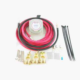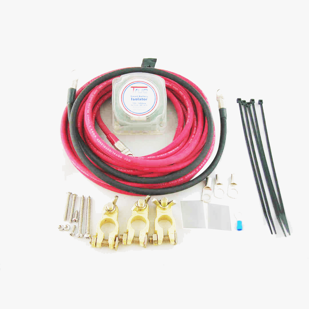


The Original Retailer of True® Dual Smart Battery Isolator

12v dual battery isolator wiring diagram – Downloadable file


True Dual Battery isolator wiring diagram for car and marine engine.


The Smart Dual Battery Isolator ambidextrous so it cannot be installed backward. Either stud can be connected to either battery’s positive terminal. This battery isolator switch wiring diagram is suitable only on True® brand.

1. Disconnect the negative terminal of your batteries
2. For the red cables – slip red insulators over small 6mm cable lugs
3. Attach lugs to the True Smart Battery Isolator studs finger tight
4. Route and connect SBI between the positive terminal of the batteries
5. Mount with screws, 3M Dual Lock, or leave it suspended
6. Route small black ground from SBI to common ground
7. Install black cable from 2nd battery to common ground
8. Tighten all connections (plastic do not over tighten)
9. Reconnect the negative terminals
10. Start the engine to verify function with SBI illumination.

Note: It is normal for LED to remain lit when the engine is first turned off. To test unit turn headlights on briefly and LED should go out. This is both for car and marine battery isolator wiring diagram.


DIRECTION FOR WIRING ON/OFF RELAY VOLTMETER

(battery isolator wiring diagram manufacturers version)

Note: These directions apply to the round and the rectangular, dual display single voltmeters.

Silver blades (2) terminal are positive (+)
Gold blade (1) terminal is negative (-)
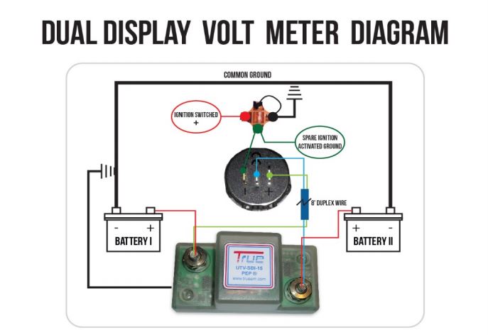
True Dual Battery isolator wiring diagram

Orange socket

Red wire – connect to switched ignition (+) power source. Something that turns on and off with the vehicle key
Green wire – One connects to the gold (-) blade on the back of the meter. The other is a spare.
Black wire – common ground (Connect last)

Dark Blue 8ft Duplex Wire

Light Blue – One end to either side of the isolator and the other end,
Light Green – one to each silver blade on the meter (Top blade is top meter).

Download 12V VSR dual battery wiring diagram for Downloadable wiring diagram for marine or boat and motor vehicles
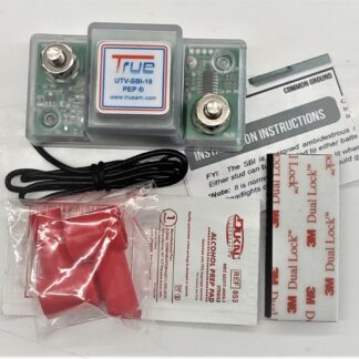

 

Power your vehicle with confidence using our 12V Dual Battery Isolator Wiring Diagram – Downloadable File. This professionally designed guide is perfect for anyone installing a dual battery system in off-road vehicles, RVs, boats, or utility setups. Whether you’re working on a Honda Pioneer 1000-5 LE, a 4×4, or a camper van, this diagram simplifies the entire wiring process and helps you avoid costly mistakes.

This easy-to-follow diagram clearly illustrates how to connect your main battery and auxiliary battery using a reliable isolator system. It ensures your starting battery remains protected while allowing your secondary battery to power accessories like lights, winches, refrigerators, and audio systems. Designed with both beginners and experienced installers in mind, the layout includes proper fuse placement, grounding points, and cable routing for optimal performance and safety.

The downloadable file is high-resolution and printable, making it convenient for garage use or on-the-go reference during installation. It’s ideal for DIY enthusiasts who want a clean, efficient setup without the guesswork. By following this diagram, you’ll achieve a system that charges both batteries when the engine is running while preventing power drain when it’s off.

Whether you’re upgrading your off-grid capabilities or simply adding reliability to your electrical system, this wiring diagram is a must-have resource. Save time, reduce installation errors, and ensure your dual battery system works exactly as intended.

Download your copy today and take the first step toward a smarter, more dependable 12V power system.

DFNA