

2nd Gen Tacoma Dual Battery Kit Wiring Diagram Explained
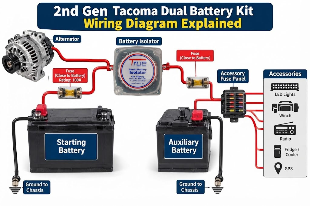
Understanding the wiring diagram of a second-generation Toyota Tacoma dual-battery system is important for knowing how its electrical components connect and work together. The 2005–2015 Toyota Tacoma is commonly modified with additional electrical equipment, including LED light bars, winches, refrigerators, radios, and camping accessories. These upgrades often require an auxiliary battery to provide additional electrical capacity.
A typical 2nd Gen Tacoma Dual Battery Kit uses a starting battery, an auxiliary battery, a smart battery isolator, connecting cables, fuses, and grounding connections. Each component has a specific position in the wiring arrangement, helping manage charging current and distribute electrical power.
Overview of the Dual Battery Wiring Diagram
The basic wiring diagram illustrates how the starting battery and auxiliary battery connect through a battery isolator. The alternator supplies charging power through the vehicle’s electrical system, while the isolator controls the connection between the two batteries.
In a conventional arrangement, the positive terminal of the starting battery connects to the isolator through an appropriately sized cable and fuse. Another protected cable connects the isolator’s auxiliary output to the positive terminal of the second battery.
Both batteries also require suitable negative connections to the vehicle’s grounding system. This completes the electrical circuit and provides the return path for current.
Identifying the Main Wiring Components
Before interpreting the wiring diagram, it helps to identify the major components. The starting battery supplies the power needed for engine starting and the vehicle’s primary electrical systems. The auxiliary battery provides additional electrical capacity for aftermarket accessories.
The smart battery isolator controls when the batteries are electrically connected. Connecting cables carry charging current between the batteries, while fuses or circuit breakers protect the wiring against excessive current caused by electrical faults.
Ground cables complete the circuit by connecting the battery negative terminals to suitable chassis or engine grounding points.
Starting Battery to Battery Isolator Connections
The starting battery is the primary connection point for the charging arrangement. Its positive terminal connects to the battery isolator through a properly sized, protected cable.
This connection allows the isolator to receive charging voltage from the vehicle’s electrical system. When the engine is running and the starting battery reaches the isolator’s activation threshold, the device allows charging current to pass toward the auxiliary battery.
The positive cable should have appropriate overcurrent protection, installed as close to the battery as practical. Cable sizing must account for current requirements and the distance between components.
Battery Isolator to Auxiliary Battery Wiring
The next section of the diagram shows the connection between the battery isolator and the auxiliary battery. A separate positive cable connects the isolator’s auxiliary output to the second battery’s positive terminal.
When the isolator activates, charging current flows through this cable to replenish the auxiliary battery. When the engine is switched off and the isolator detects the appropriate disconnect condition, it separates the batteries.
This arrangement helps prevent accessories connected to the auxiliary battery from unnecessarily draining the Tacoma’s starting battery.
Alternator Charging Circuit Explained
The alternator supplies electrical power while the engine is operating. In a conventional Tacoma dual-battery arrangement, its output maintains the starting battery and supports the vehicle’s electrical loads.
Once the charging voltage reaches the isolator’s activation threshold, the auxiliary battery can also receive charging current.
The wiring diagram therefore represents a shared charging arrangement controlled by the isolator rather than two completely independent charging systems. Battery chemistry and charging requirements must be considered when selecting the appropriate isolator or charging device.
Ground Connections and Fuse Protection
Ground connections are essential parts of the wiring layout. Both battery negative terminals must have suitable connections to the vehicle’s grounding system, using properly sized cables and clean, secure connection points.
Fuse protection is equally important. The positive cables connecting the batteries and isolator need appropriate protection to reduce the risk of wiring damage during an electrical fault.
Incorrect cable sizing, inadequate grounding, and poorly positioned fuses can compromise the reliability and safety of the entire installation.
Auxiliary Battery Connections for Electrical Accessories
The auxiliary battery typically supplies additional equipment such as refrigerators, LED lighting, radios, USB charging outlets, and other aftermarket accessories.
These connections are generally routed through appropriately rated fuses or a power distribution panel. This allows individual accessories to have suitable circuit protection without placing unnecessary demands on the starting battery.
High-current equipment requires particular attention to cable sizing, fuse ratings, and manufacturer specifications.
How the Complete Dual Battery Wiring System Works
When all connections are properly configured, the system operates as an integrated electrical arrangement. The alternator charges the starting battery, and the smart isolator connects the auxiliary battery when the required voltage conditions are met.
When the engine stops, the isolator separates the batteries according to its programmed operating thresholds. Accessories connected to the auxiliary battery can continue operating without directly consuming the starting battery’s reserve.
A properly designed 2nd Gen Tacoma Dual Battery Kit brings these components together through an organized wiring arrangement. Understanding the diagram helps Tacoma owners recognize the purpose of each connection and appreciate why correct cable sizing, grounding, fuse protection, and component compatibility are essential for dependable operation.
Recent Posts
- What Is the Difference Between an Automatic and Manual Honda Pioneer Battery Isolator?
- When a Basic Split Charge Relay Kit Isn’t Enough
- UTV ATV Dual Battery Isolator Kit Wiring Diagram Explained
- When Does an Overlanding 4Runner Actually Need a Dual Battery Kit?
- When Should You Upgrade Your 4Runner to a Dual Battery System?
- What to Look for in a Dual Battery Kit for Truck: Essential Features Explained
- How to Choose the Best GM Dual Battery Kit for Your Truck or SUV
- Why a Modified GMT400 May Need a GMT400 Dual Battery Kit
- From Battery Isolators to Intelligent Power Management: Where Automotive Technology Is Heading
- When Should You Upgrade to a GMT800 Dual Battery Kit vs. Running a High-Output Alternator Alone?